Settings
File Structure
cspy
└───settings
|   └───settings.json: example settings file
|   └───qscope_L.json: settings file for left table
|   └───qscope_R.json: settings file for right table
└───run_keystone.py: script for keystone calibration
└───run_scanner.py: start script for the program
└───cityscopy.py: application program for tag decoding
settings.json
For both the execution of the keystone calibration and the scanning, a settings file has to be provided. (You can select the settings file by appending it to the python execution command like so: python3 run_scanner.py settings/qscope_L.json) Here is an example of what that file looks like. Detailed description of each of the keys will follow below.
{
    "PORT": 5001,
    "table_name": "L",
    "nrows": 19,
    "ncols": 22,
    "grid_w": 1920,
    "grid_h": 900,
    "cam_id": 0,
    "realsense": {
        "device_num": 1,
        "active": true,
        "exposure": 478.0,
        "gain": 2
    },
    "max_l": 70,
    "max_a": 255,
    "max_b": 132,
    "gradient_min": 0.96,
    "gradient_max": 0.64,
    "quantile": 0.53,
    "interval": 500,
    "gui": true,
    "tag_length": 4,
    "tags": [
        "1110",
        "1100",
        "1001",
        "1000",
        "1111",
        "0000"
    ],
    "sliders": [
        {
            "id": "slider0",
            "step_size": 0.01,
            "x_min": 8,
            "x_max": 104,
            "y": 326,
            "slider_l": 64,
            "slider_a": 255,
            "slider_b": 132
        },
        {
            "id": "slider1",
            "step_size": 0.01,
            "x_min": 278,
            "x_max": 555,
            "y": 324,
            "slider_l": 58,
            "slider_a": 255,
            "slider_b": 132
        }
    ],
    "mirror_cam": true,
    "rotate_image": false
}
All of these values can be set initialially using the json file or during the program’s runtime.
General
The PORT defines the communication port between the decoder and the frontend application. Make sure you configure this to match the frontends grid objects’ settings!
table_name is used to differentiate different instances of cspy.
interval just defines the interval of scans in ms. This will also be the minimum interval of messages sent from cspy to the frontend.
gui toggles the visibility of calibration tool tips.
grid setup
nrows and ncols relate to the extent of the physical grid, while grid_w and grid_h represent the dimensions of width and height of the virtual grid to be spawned (and observed).
camera setup
cam_id is used for the differentiation of multiple cameras. The realsense settings are only important when using (multiple) realsense cameras. When using any other camera, set active to false !
light and detection settings
max_l, max_a and max_b are threshold values for the CIELAB color space. gradient_min and gradient_max together define the end points of a grey color overlay used to even out uneven light conditions. quantile is a threshold value determining the color based on te distribution of b/w values in the image.
programming the tags
tag_length is the resolution of tags. We only used 4-bit values, but it is possible to work with more complex tags by splitting each grid cell into more than four areas to be scanned. tags is a list of possible tags. For each entry, 1 is for “black” and 0 corresponds to “white”. Note that the order of the tags is important, since the cells represented in the frontend will get their :ref:`ID<frontend_grid>` from the index of the tag in this list! The four digits are read like this: 1. upper left, 2. upper right, 3. lower left, 4. lower right.

From left to right, these tangibles have the tags:
“0101” - which is the same as “1100” (ID 1), but rotated
“1000” - ID 3
“0110” - ID 2, rotated
“1110” - ID 0
(see list above for comparison)
Slider
Additionally to the decoding of the grid of tiles, cspy can monitor slider objects, to facilitate gradual setting of values by the user.
The slider objects look for the set of darkest pixels around a white line that can be positioned anywhere on the image. Each slider has its own luminance sensitivities and thresholds that can be set individually (like explained above).
The physical slider is just an acrylic plate with a dark underside that can be moved along a slid - the position will be detected and converted to a float between 0 and 1 analogous to the position of the physical slider (→ darkest pixels) relative to the length of the white line. The information is sent via UDP to the frontend and will be processed there.
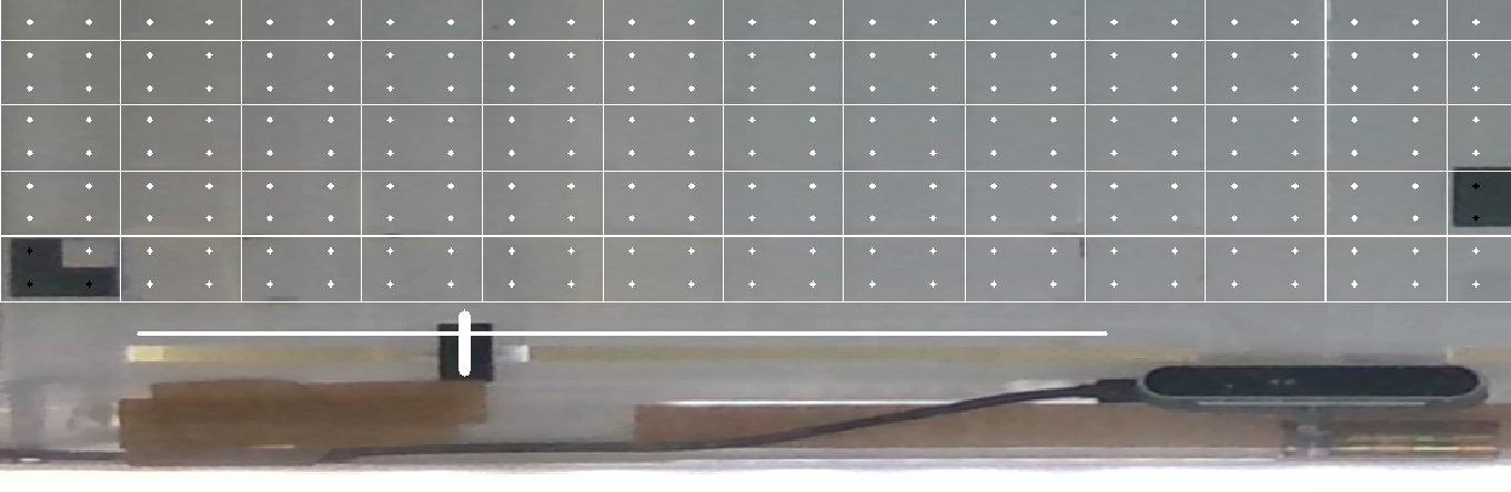
Hint
Recommendation: place y-position of slider slightly ABOVE the slid, so you don’t try to decode what’s on the ceiling and other interferences with people. Also, it is recommended to position the white line within a big enough distance from the camera itself, since the darkness of the camera will interfere with the detection (see image above).